New Curio Cabinet Display (Project)

New Curio Cabinet Display (Project)
Sometimes, life gets hectic. This implies that you may not always be able to construct models. Because I typically have plenty of spare time, I get to create a lot—or, more recently, build and blog. However, there hasn't been much spare time these past few weeks. It's been a while since I've constructed any models because I've had a lot of housework chores come up all at once. One of those tasks, though, was completing the LED lighting solution for the curio cabinet my in-laws gave me some time ago.
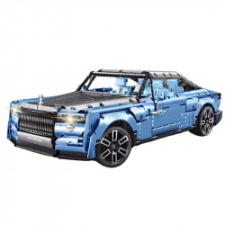
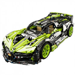
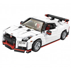
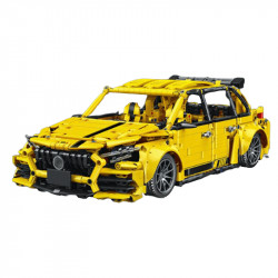
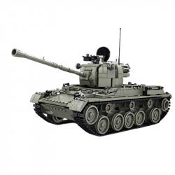
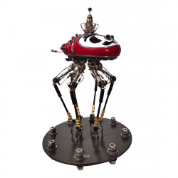
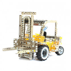
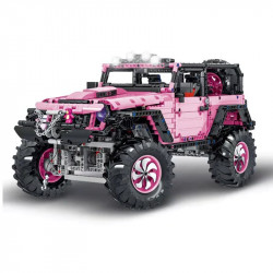
I've been keeping my larger models—almost all of my Piececool and ICONX/Premier Series models—in a half-curio cabinet for a long time, but it has its problems because of a furniture outlet. The largest of these included extensive framing and enormous groove patterns in all but one window. It was really challenging to look at the models. When my in-laws offered a curio they were no longer using, I was overjoyed. Although there was some illumination included, I chose to go all out so I didn't have to pay for the curio itself. So there was LED strip lighting.
However, in order to illuminate the models, I required a good technique to install the LED strips. Thus started a protracted process of brainstorming, plotting, pondering, and weeding out bad ideas. In the end, I did buy a set of LED strips that I liked and that wasn't too costly. Then, thinking I could mount it, I purchased some metal corner protectors for the corners of the walls. However, as I began attempting to determine the precise mechanisms... I saw that it was a bad idea. Since I didn't want to be blinded by a lot of reflected LED spots, I finally caved in and purchased some aluminium LED channels with diffuser covers. I ended up spending money because I was attempting to do things as cheaply as possible. That's life.
It wasn't complicated enough, though! Not for me, please! But really... I always come up with methods to lengthen and complicate projects. In this instance, I made the decision that I didn't like the concept of being blinded by the LED lights' reflections in the mirror at the back of the curio. Indeed, I was fixated on the blinding object. I decided to cover the mirror with something. Originally, icing or window tinting would have been used, but such options are costly. Butcher paper came to mind next, but it didn't sound very appetizing. At last, tissue paper might be a viable and inexpensive alternative! You know, the stuff for gift bags.
To try this, I diluted white glue and applied it to tissue paper and glass from a broken picture frame I had sitting around. It worked so well that I decided to find some black tissue paper since I thought it would provide a striking contrast. I visited Dollar Tree, but all they had were white and pastels. Before finding any black, I drove around the rest of the town, stopping at a few places and buying some white just in case I couldn't find any. Then, before I actually began, I understood that everything would turn dark since the black would absorb all the light. So, in the end, I used the white. And it was the proper choice.
My initial plan was to apply the tissue paper and attempt to smooth it out exactly, but I quickly realized that this would be far too much labour when I tried to do it on the actual curio. I chose to accept the outcome because the tissue paper's creases gave it a marbling/crackled appearance, which was a benefit rather than a drawback. Additionally, I decided to ignore the amusing appearance of the overlapped areas. There are moments when you have to accept that perfection is not possible, much as while making the models. In order to get some of the lighting to reflect up on the underside of buildings, I also chose to "opaque" the shelves while I was at it—a lot of labour.
Naturally, I had to find out how to set up the V-channel before I could start on any of that. Additionally, I had initially discovered a few "joint" pieces that could be joined to form L-shapes. Although it was near, it wasn't quite what I wanted. When I ordered my V-channel, those were regrettably no longer available. This project was cursed, ugh! Thus... I searched endlessly for a different option. And was unable to locate one. I was starting to lose hope. Until I recalled that I was proficient in TinkerCAD design and owned a 3D printer. I then started a new phase of this endeavour. Despite going through a few test prints along the route, I ultimately produced three distinct joint kinds.
The LED strips needed to be chopped up and soldered at last! Sort of. I started by cutting some wires to create pigtails. Then, I measured and planned a lot and created cut lists, schematics, and other things. I then divided the LED strips into pieces. Additionally, I made the proper cuts to the metal V-channel.
Additionally, I attached 18 gauge solid-core wire "pigtails" to the ends of the LED strip segments using solder. I then connected them to the channelling and began joining pieces of these with solder. I was thrilled because everything was coming together! To further safeguard the soldered points, I covered them with liquid electrical tape and then began connecting the portions collectively. This is when the contact points for soldering onto the LED strips started to come loose, along with the wires.
This endeavour was doomed, indeed. You could no longer solder onto the end of the strip when the contact points came off. I was heartbroken. I believed I had just squandered a whole set of LED strips, a lot of cables, and countless hours. It turns out that I just needed a little sleep. Because I had a flash of insight a few days later, the entire strip can still be illuminated by using contact points farther in from the end. I thus removed all of the old wire and painted rubber from the strips and purchased some new 20 gauge stranded wire (really, I was getting 22 gauge, but I thought I was getting 20).
I then started soldering once more. However, I made use of the more pliable stranded wire this time. Additionally, I soldered to contact points on either side of a cut mark, which was farther in the strip and allowed me to solder to two at once. Additionally, the wires were hot-glued into place at the end of the V-channel after being run separately along each side of the LED strip. By doing this, I could ensure that the hot glue holding the wires in place would not be stressed instead of the actual contact site. Cheers! Proceed to solder the segments into lighting strips or channel sections. After soldering parts together, I had two LED strip assemblies that were prepared for the curio. That is after I corrected the area where I had crossed-wired the positive and negative, which is not ideal for LEDs.
However, I did have some things prepared after that! It's time to get together. And my goodness, that was harder than I had anticipated. There is a lot of v-channel insertion into joints, balancing, and swearing. After that, there was more balancing, re-inserting the v-channeling that had fallen out, re-balancing, putting the diffuser screens back on, re-balancing, and then realizing that I had mismeasured, throwing out some of the joints, balancing glass shelves and hoping they wouldn't break, balancing v-channel, and keeping re-inserting v-channel into joints. Additionally, I was too exhausted to adjust the crooked mounting of some items at the time, which is driving me crazy.
Projects can, therefore, go awry and consume far more of your time than you had anticipated. And that's only one of the numerous projects I'm working on. At least most of them are good projects! Such as assembling my brand-new 3D printer and producing my first "large" print. I also decided that the first print should be for my wife because she is the best. She intends to paint the gloves since she adores her "little" Bernie. Yes, she really enjoyed the meme.
